Simple Robotics Projects With Circuit Diagram Schematic File. teensy_robot.zip. Conclusion. In this article I outlined the requirements for the robot and my design choices to meet those requirements. These choices led to a schematic and bill of materials (BOM) to add up the costs for the project. In part 2 of this series, I'll draw the circuit board so it can be manufactured!

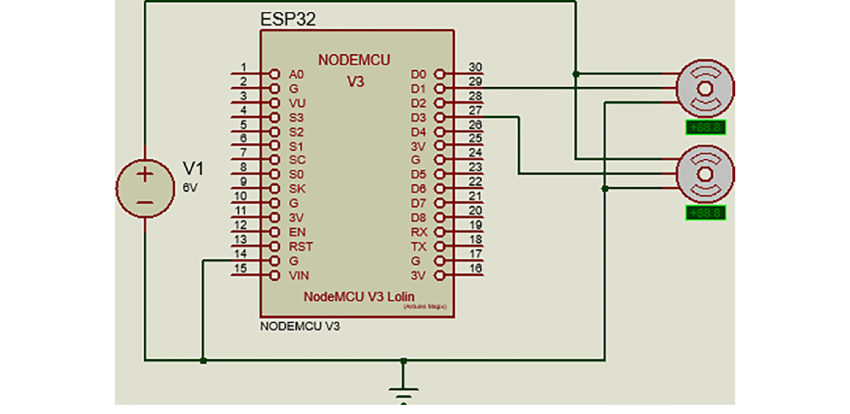
Above, you can see the circuit diagram of this maze-solving robot. It is self-explanatory, as we have provided a clear diagram with all the components marked. For added clarity, I am detailing the circuit below: Since we are using the motor shield v1, we are limited to using the analog pins. Therefore, I am using A0, A1, and A2 as digital
Simple Robot Schematic Diagram Circuit Diagram
The receiver and motor driver circuit (Fig. 3) is built around Arduino UNO board (BOARD1), decoder IC HT12D (IC2), 433MHz RF receiver module (RX1), motor driver IC L293D (IC3), regulator IC 7805 (IC4) and a few discrete components. Fig. 1: Block diagram of Arduino based RF controlled robot Fig. 2: Circuit of transmitter section Arduino UNO board
Circuit Diagram. Making the connections for this Arduino based Self balancing Robot is pretty simple. This is a self balancing robot using Arduino and MPU6050 so we ave to interface the MPU6050 with Arduino and connect the motors though the Motor driver module. The whole set-up is powered by the 7.4V li-ion battery.

How To Build Your Own Arduino Based Robot Circuit Diagram
Explore 75+ DIY robotics projects with detailed circuit diagrams, source code, and complete instructions.Whether you're a beginner or an advanced maker, you'll find exciting projects using Arduino, Raspberry Pi, ESP32, and other microcontrollers.From line-following robots to AI-powered bots, our tutorials make robotics easy to learn and build. A schematic is a wiring diagram that tells you where to attach wires to all the parts in your circuit. A schematic, to the uninitiated, can be a little overwhelming at first. So instead of possibly confusing you, I invented what I call a colored dot schematic. I'm willing to bet a 3 year old can understand this enough to build the circuit . . .